Dynamic Host Configuration Protocol (DHCP)
Dynamic Host Configuration Protocol (DHCP)
Overview
Dynamic Host Configuration Protocol (DHCP) is a network management protocol used on Internet Protocol (IP) networks to automatically assign IP addresses and other communication parameters to devices connected to the network using a client-server architecture.
Protocol
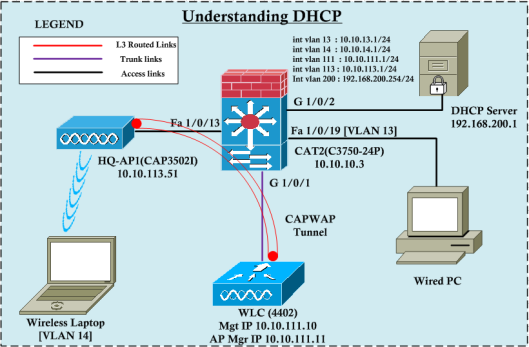
The figure below shows the Switch, WLC, AP & DHCP server (Microsoft DHCP server on VM). The Switch has been configured with a basic SVI interface with the gateway address listed.
DHCP discovery
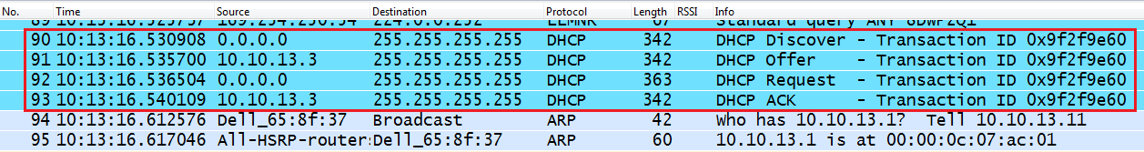
The image below illustrates how DHCP works in a wired environment by capturing wireshark packets from the wired computer's Ethernet interface while it is getting an IP from a DHCP server. As you can see, there are 4 types of packets (Discover, Offer, Request, ACK, i.e. DORA) exchanged before the computer gets an IP.
As you can see at layer 4, it uses the UDP protocol with src port 68 and des port 67, corresponding to bootpc (client) and bootps (server). In fact, DHCP is an extension of the BootP protocol. This discovery message includes certain options (53, 61, 12, 60, 55), sometimes these fields are used to identify the client to the DHCP server. At layer 3, src will be 0.0.0.0 (because there is no IP yet) and dst (255.255.255.255) will be all the broadcast subnets. At layer 2, src MAC will be the PC's NIC MAC address, while dst MAC will be the broadcast MAC address.
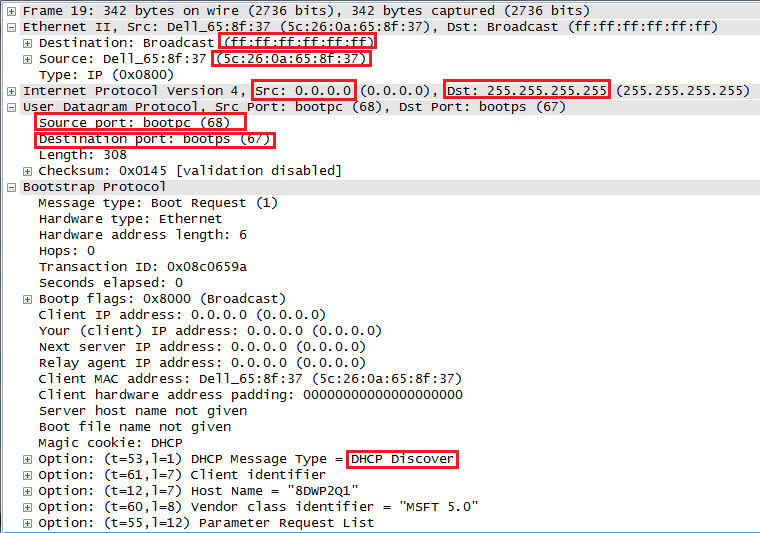
This layer 2 broadcast message will be sent to all hosts in that subnet and will reach the switch's SVI (int vlan 13-GW). Since the DHCP server is in a different subnet (vlan 200), this DHCP discover message will not reach there (the broadcast message will be limited to the local subnet). The DHCP server will then send a DHCP offer message.
DHCP offer
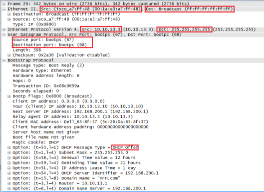
When the switch acts as DHCP-Relay (note that the switch's vlan 13 IP address is listed as the relay-agent IP address in this packet), it will receive a DHCP offer message from the DHCP server and then send it to the client. This packet includes Bootp options such as IP address, subnet mask, lease time, DHCP server IP, domain name, default gateway, etc. The UDP source port will be 67 (from the server) and the destination port will be 68 (to the client). At layer 3, the switch will set its vlan 13 IP address as the source IP of this packet and the destination IP will be the layer 3 broadcast (255.255.255.255). At layer 2, it will be sent as a broadcast frame.
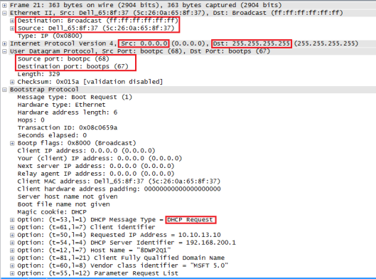
DHCP request
When the client receives this offer message, it sends a DCHP request message to request that IP. The client now knows what the "offered client IP" in the DHCP message is, and so the "Request Message" will include that IP (in this case, 10.10.13.10). It also lists the DHCP server address (this way, even if multiple DHCP servers respond, the client can still choose which DHCP server to request the IP from). Since the traffic is coming from the client, the UDP source port will be 68 and the destination port will be 67. However, the layer 3 source port will be 0.0.0.0 and the destination will be 255.255.255.255. At layer two, this message will be broadcast.
DHCP ack
Finally, the client will receive a DHCP ACK, confirming that it can use this requested IP. However, this destination IP packet is still a layer 3 broadcast packet (since the client does not have an IP) and therefore a layer 2 frame is also broadcast.
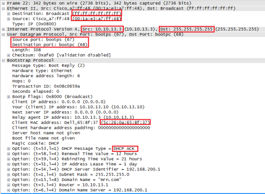
When the client receives this frame and processes it, it can confirm that its MAC address is listed as the client MAC in the bootp field. It will then assign the given IP to the NIC. As you can see, the next thing it will do is send an ARP request to find the gateway MAC address (10.10.13.1 is listed in the bootp option). The client will then know everything (layer 2 and 3) to communicate with the rest of the network.
References
[1] https://mrncciew.com/2012/12/27/understanding-dhcp/
This post is licensed under CC BY 4.0 by the author.