WLAN Technology Basics
WLAN Technology Basics
Radio Waves
Wireless communication involves the transmission of information over the air by radio waves, which radiate and propagate through space.
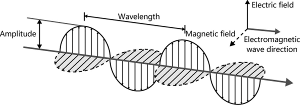
Radio waves are a type of electromagnetic wave capable of transmitting energy and momentum over the air through the use of electric and magnetic fields whose oscillations are in the same phase but both perpendicular to each other and to the direction of propagation. Electromagnetic waves travel at the speed of light.
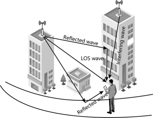
Electromagnetic waves are continuously emitted from the everyday objects around us and propagate outward in all directions where they are reflected, refracted, or scattered. In wireless communication, multiple identical electromagnetic waves emitted from a transmitter itself (known as multipath interference) due to direct radiation (LOS propagation) and reflection, in addition to the electromagnetic waves originating from other sources, result in interference on the receiver end, wireless communication is far more complex than traditional wired communication.
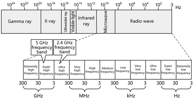
Frequency is an important parameter of electromagnetic waves and its distribution is referred to as “spectrum.” In order of decreasing frequency, electromagnetic waves can be classified into gamma rays, X-rays, ultraviolet rays, visible lights, infrared rays, microwaves, and radio waves, as illustrated in below Figure. Fligher-frequency electromagnetic waves are more energetic, exhibit stronger direct radiation capabilities, but feature faster energy attenuation during transmission and shorter transmission distances.
WLANs utilize radio waves. A radio wave is generated by an oscillation circuit’s alternating current and can be transmitted and received over an antenna. It is also referred to as radio, electric wave, or radio frequency (RF).
The frequency range of a radio wave is known as the frequency band. WLANs operate in the 2.4 GHz (2.4-2.4835 GHz) or 5 GHz (5.15-5.35 GHz or 5.725-5.85 GHz) frequency band. Designed for Industrial, Scientific, and Medical (ISM) purposes, these frequency bands can be used without obtaining license or paying fees as long as the transmit power requirement (generally less than 1 W) is met and no interference is caused to other frequency bands. While such cost-free resources reduce WLAN deployment costs, cochannel interference can arise when multiple wireless communications technologies operate within the same frequency band. Available ISM frequency bands vary depending on country and region, and WLANs are required to use frequency bands in compliance with local laws and regulations.
Wireless Communications System
Before we explore how information is transmitted through radio waves, let’s take a look at an example of sound transmission, as this will help understand the composition of a wireless communications system. When A says “Hello” to B, A is actually sending an instruction to the mouth to generate sound, which then converts the information into a group of sound waves with a specific frequency and amplitude. The sound waves vibrate and propagate through space until they reach B’s ears and are converted into identifiable information.
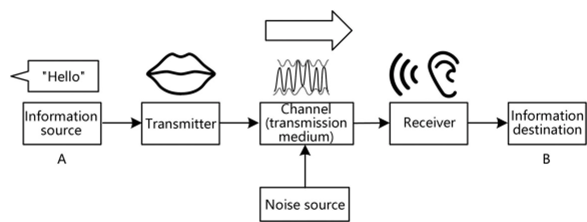
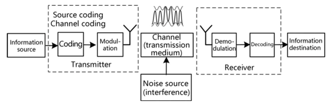
The sound transmission process in our example is a type of communications system. A is the information source, and “Hello” is the information to be transmitted. Here, A’s mouth is the transmitter used to convert the information into sound waves by means of modulation. The waves are then transmitted over the air, which functions as the channel (or transmission medium). B’s ears serve as the sound wave receiver, and В as the information destination converts sound waves into identifiable information by means of demodulation. During the sound wave transmission, speech from other people may result in noise or interference, possibly leading to В failing to clearly hear A’s message.
In a wireless communications system, information to be transmitted can include images, text, or sound. A transmitter applies source coding to first convert the information into digital signals that allow for circuit calculation and processing, and then into radio waves by means of channel coding and modulation, as illustrated in the below Figure. Transmitters and receivers are connected through interfaces and channels. Unlike the visible interfaces involving cable connections used for wired communication, wireless interfaces are invisible and connected over the air. As such, a wireless interface is referred to as an air interface.
Source Coding
Source coding is the process of converting raw information into digital signals by using a coding scheme. Source coding can minimize redundant raw information by compressing the information to the maximum extent without causing distortion. Different types of information require different coding schemes (e.g., H.264 for videos).
Channel Coding
Channel coding is a technology used for detecting and correcting information errors in order to improve channel transmission reliability. As we have seen in our example, wireless transmission is prone to noise interference, and this can lead to errors in the information delivered to the receiver. Channel coding is utilized to restore information to the maximum extent at the receiver end, thereby reducing the bit error rate. Binary convolutional coding (BCC) and low-density parity-check (LDPC) code can be used for WLAN channel coding.
Channel coding adds redundant data to the raw information, increasing the information length. The ratio of the number of precoding bits (raw information) to the number of postcoding bits is referred to as the coding efficiency. Channel coding decreases the transmission rate but increases the transmission success rate of valid information. As such, selecting a proper coding scheme for communication protocols is crucial to achieving an optimal tradeoff between performance and accuracy.
Modulation
Digital signals in circuits are instantaneous changes between high and low levels. Only after being superimposed on high-frequency signals generated by high-frequency oscillation circuits, the digital signals can be converted into radio waves over antennas and then transmitted. This process of superimposition is known as modulation. Having no information itself, a high-frequency signal instead carries information and is therefore called a carrier.
The modulation process encompasses both symbol mapping and carrier modulation.
Symbol mapping involves mapping bits of digital signals to symbols (also referred to as code elements or information elements) by modulation, with each symbol representing one or many bits. For example, one symbol carries one bit, two bits, and four bits with binary phase shift keying (BPSK), quadrature phase shift keying (QPSK), and 16 quadrature amplitude modulation (16QAM), respectively. A larger quantity of bits carried in a single symbol indicates a higher data transmission rate.
Carrier modulation refers to the process of superimposing symbols and carriers, ensuring that the carriers are carrying the information to be transmitted. Multicarrier modulation can be used to further improve the transmission rate and works by taking advantage of the orthogonal characteristics of waves to split signals into several groups, with each modulated over separate carriers, and then combine the modulated signals for transmission over antennas, achieving concurrent transmission of multiple groups of signals. Multicarrier modulation can effectively utilize spectrum resources and reduce multipath interference. Orthogonal frequency division multiplexing (OFDM) is the multicarrier modulation technology used in WLANs.
Channel
A channel transmits information, and a radio channel is a radio wave in space. Given that radio waves are ubiquitous, random use of spectrum resources will result in endless interference issues. Therefore, in addition to defining usable frequency bands, wireless communication protocols must also accurately divide frequency ranges, with each frequency range known as a channel.
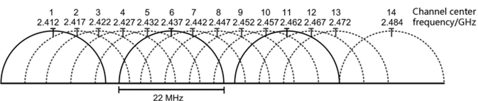
For example, the WLAN 2.4 GHz frequency band is divided into 14 channels with overlapping or nonoverlapping relationships, each with a bandwidth of 22 MHz, as illustrated in the below.
- Overlapping channels, such as channel 1 and channel 2, interfere with each other.
- Nonoverlapping channels, such as channel 1 and channel 6, can coexist in the same space without interfering with each other.
Channel Rate and Bandwidth
Wireless communication requires both a high channel transmission rate and a low error rate. The channel transmission rate, in unit of bps, is referred to as the data or bit rate, while the maximum rate that can be achieved on a channel is known as the channel capacity or throughput.
Bandwidth, also referred to as frequency or spectrum width, is a contiguous frequency range representing the amount of spectrum resources available (displayed in units of Hz). In some cases, bandwidth can also indicate the channel capacity. This is in accordance with the Nyquist theorem: in an ideal situation where noise can be ignored, if the channel bandwidth is В (unit: Hz), the symbol rate will be В multiplied by 2 (unit: Baud) and then the channel capacity can be obtained based on the number of bits mapped to symbols. For example, if the frequency range of one channel is 5170-5190 MHz and one symbol carries six bits, the bandwidth is 20 MHz and the maximum theoretical rate is 240 Mbps. As a result, a bandwidth can indicate a rate and a spectrum segment width.
While the Nyquist theorem describes a perfect channel without noise, in reality, noise is omnipresent. The Shannon theorem tells us that the actual channel capacity is susceptible to noise, the impact of which may be represented by the signal-to-noise ratio (SNR), that is, the ratio of signal power to noise power. For a given bandwidth, larger noise indicates less channel capacity. However, according to the Shannon theorem, when the bandwidth tends to infinity, channel capacity does not increase infinitely.
References
[1] https://ebrary.net/194981/computer_science/channel_bonding#69171
This post is licensed under CC BY 4.0 by the author.